
5.0
Owner's of the A.O. Smith Boiler VB/VW- 1000 gave it a score of 5.0 out of 5. Here's how the scores stacked up:

9
WATER TEMPERATURE LIMIT CONTROLS
The“V(B/W)”modelsincorporateanoutletwaterprobeconsisting
of two limit controls:
1. A Manual Reset High limit control that can be set as high as either
210°F(99°C)or235°F(113°C),dependingontheapplication.
2. Axedmanualhighlimit,factorysetat244°F(118°C).If
the manual reset should open due to high temperature, the
gas valves will close and unit will go into lockout. If lockout
occurs, push the SELECTION button on UIM to restart boiler.
ON/OFF SWITCH
The ON/OFF Switch is a single-pole, sin gle-throw rocker switch.
This switch pro vides 120V from the line source to the boiler.
CIRCULATING PUMP
HOT WATER SUPPLY BOILER-VW, the circu lating pump is
integral to the VW models. This pump has been lu bricated
at the factory, and future lu brication should be in accordance
with the motor manufacturer’s instructions provided as a
supplement to this manual.
HOT WATER HEATING BOILERS-VB, the cir culating pump is NOT
providedonstandardmodels(optional)andmustbeobtainedand
installedintheeld.
NOTE: If a system pump is to be installed on a VB model,
the maximum rating of pump motor must not exceed 1 hp.
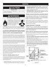
TEMPERATURE PROBES
INLET / REMOTE
TEMPERATURE
PROBE
OUTLET
TEMPERATURE
PROBE
INLET / REMOTE
TEMPERATURE
PROBE
OUTLET TEMPERATURE
PROBE
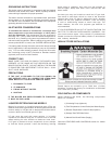
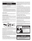
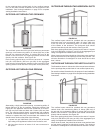
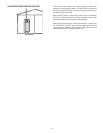
FIGURE 7. REMOTE PROBE INSTALLATION.
Temperature probes are 3/4 inch male NPT threaded immersion
probes, see Figure 7. Temperature probes have embedded
temperaturesensors(thermistors).Theboiler’scontrolsystem
monitors these sensors to determine water temperature at various
points in the system.
INLET AND OUTLET TEMPERATURE PROBES
All VF boilers have one Inlet and one Outlet Temperature Probe
factory installed in the top of the heat exchanger to monitor the
water temperature entering and leaving the boiler. The Inlet Probe
is a temperature sensor only and has two leads. The Outlet probe
also contains the manual reset high temperature limit switch and
has four leads. The control system displays the Inlet and Outlet
water temperatures sensed from these two probes on the default
Temperatures screen.
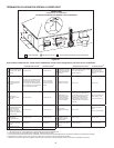
REMOTE TEMPERATURE PROBE
All VF boilers are supplied from the factory with a Remote
Temperature Probe. The supplied Remote Temperature Probe
is used to control system water temperature for a single boiler
in a domestic hot water storage tank or in the return line from a
primary/secondary hydronic heating system. Use of the Remote
Temperature Probe allows a boiler to sense the actual water
temperature inside the storage tank or hydronic heating loop.
The boiler will modulate its firing rate in response to the
actual system temperature and load conditions. The control
system displays the temperature sensed from the Remote
TemperatureProbeasthe“Tank”temperatureonthedefault
Temperatures screen.
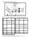
QUAD THERMISTOR PROBE
When connecting up to 4 boilers to a single storage tank
or one primary/secondary hydronic heating system the
optional Quad Thermistor Probe should be used. The Quad
Thermistor Probe is a remote temperature probe with four
temperature sensors embedded in one device. The Quad Thermistor
Probe allows up to 4 boilers to sense system temperature from
same point in the system. Use of the Quad Thermistor Probe
will allow each connected boiler to individually sense actual
water temperature in the storage tank or hydronic heating loop.
The temperatures sensed from each of the four temperature
sensorcircuitsinaQuadThermistorProbeareshownas“Tank”
temperature on each boiler’s default Temperatures screen.
NOTE: See the Field Wiring, Remote Temperature Probe
Installation and the Primary System Control sections of this manual
for operating and installation instructions.
LOW WATER CUTOFF (OPTIONAL)
If boiler is installed above radiation level, a Low Water Cutoff Device
must be installed in boiler outlet at time of installation or, order
pre-installed from the factory. If low water detection is required by
authorities having jurisdiction, a low water cutoff switch should be
installed in the boiler outlet water line. The switch should receive
periodic(everysixmonths)inspectiontoassureproperoperation.
PRESSURE RELIEF VALVE
An ASME rated pressure relief valve is furnished with the boiler.
Neveroperatetheboilerifitisnotlledwithwaterandaproperly
sized pressure relief valve is not installed.
The pressure rating of the relief valve should be equal to or less
than the rated pressure capacity of any component in the system
including the boiler. Should the valve need to be replaced, call
the toll free phone number listed on the back of this manual for
further technical assistance.
Explosion Hazard
Relief Valve must comply with
ASME code.
Properly sized
Relief Valve must
be installed.
Can result in overheating and
excessive tank pressure.
Can cause serious injury or death.
A discharge pipe from the relief valve should terminate at an adequate
oordrain.Donotthread,plug,orcaptheendofdrainline.
CAUTION
•
Pressure Relief Valve discharge pipe must
terminate at adequate drain.
Water Damage Hazard


Find Your Products By Category
Please Login
