
5.0
Owner's of the A.O. Smith Boiler VB/VW- 1000 gave it a score of 5.0 out of 5. Here's how the scores stacked up:

38
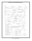
INPUTS TO MCB
TEMPERATURE SENSORS:
Temperature probes (MCB-outletandeitherinletortankare
required):TheMCBacceptsanalogtemperatureinputsfrom
uptothreesensors(inlet,outlet,andtank).
MRHL(ManualResetHIGHLIMIT):TheMRHLisahi-limitswitch
located inside the outlet probe. It is a normally closed switch that
opens if the probe is exposed to a temperature higher than the trip
point. Once tripped, the control system needs to be manually reset.
Thermostat input(MCB-optional):Thisinputissetuptoworkwith
an externally connected thermostat that provides a contact closure. If
this input is closed and everything else is in the proper state, a “call for
heat”conditionwillbeinitiated.Theseleadsshouldbeshortedtogether
when a thermostat is not being used. If it is desired that the thermostat
control the temperature of the boiler, the operating setpoint of the
system should be set higher than the temperature that the thermostat is
controlling. This will allow the thermostat to control the boiler. When the
thermostat closes, a call for heat will be generated until the thermostat
determines that the required temperature has been reached.
AIR PRESSURE SENSORS (OPEN CONDITION INDICATES FAULT):
Blocked Inlet (MCB-required)Normallyclosedswitchthat
activates if the air inlet is blocked 3/4 or more during operation.
Blocked Flue(MCB-required):Normallyclosedswitchthatopens
iftheuebecomesblockedduringoperation.
Blower Prover(MCB-required):Normallyopenswitchthatcloses
when the air pressure produced by the blower is above the set point.
GAS PRESSURE SENSORS (OPEN CONDITION INDICATES FAULT):
Low Gas(MCB-required):Normallyopenswitchthatcloseswhen
the gas pressure rises above the trip level. This input is enabled/
disabled by a dip switch on the MCB
Hi Gas(MCB-required):Normallyclosedswitchthatopensifthe
gas pressure exceeds a set value. This input is enabled/disabled
by a dip switch on the MCB.
WATER LEVEL SENSOR (OPEN CONDITION INDICATES FAULT):
Low Water Cut Off(MCB-optional):Normallyopenswitchthat
closes when water reaches preset level. This input is enabled/
disabled by a dip switch on the MCB.
WATER FLOW SENSOR:
Flow(MCB-required):Normallyopenswitchthatcloseswhen
owexceedsasetvalue.
FLAME SENSOR:
Flame(MCB-required):Returnsasignaltothemicroprocessor
ifameisdetectedontheburner.Iftheamerodismissingor
shorted,theamewillnotbedetected.
OUTPUTS FROM MCB
RELAY CONTACT OUTPUT:
Alarm (MCB-24VAC-optional):Provideselectricalpowerto
operateanexternalalarm.Thiscanbeanaudiodevice (i.e.,
Sonalert),avisualdevice(lamp),oranyother devicethatwill
operate with the voltage and current level provided.
Pump(MCB-120VAC-requiredonsystemsthatdonothave
anexternalpump):Provideselectricalpowertodirectlyoperatea
pump or the coil of an externally connected contactor.
Blower(MCB-120VAC-required):Variablespeedblowersutilize
the high blower output only.
Igniter(MCB-120VAC-required):Providespowertooperate
the HSI igniters.
Gas Valve(MCB-24VAC-required):Providespowertoactivate
the gas valve. The gas valve cannot be activated when the MRHL
contacts are open.
Low Water Cut Off(MCB-24VAC-optional):Directlyconnectedto
the 24VAC line to provide power to operate an external LWCO device.
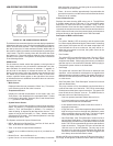
MCB AND PDB INDICATOR LAMPS AND FUSES
A green LED is mounted on the PDB to indicate when line voltage
isapplied(thePDBalsocontainsayellowandredLED,andatest/
run jumper that are used during installation to verify proper power
connections).AredLEDontheMCBisusedtoindicatewhenthe
24VAC input fuse has blown.
Yellow LEDs are located near the microcontrollers on the MCB.
TheseLEDsare“heartbeatindicators,”andblinkapproximately
twice per second to indicate that the microcontrollers are
running.
MCB JUMPERS
The MCB has two jumpers. JP1 on the MCB is used to terminate
the external communications line. It is normally left off and installed
when the external cable is very long.
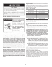
IGNITERS
The EMC modulation system operates with Silicon Carbide Igniters
MCB - Ten Position Dipswitch:
DipswitchcongurationsareREAD ONLY ON POWER UP. These switches are only to be set at the factory or by authorized trained
personnel! Once set the boiler will operate according to the chosen options. If a switch is changed, power must be cycled before the
change will take effect. The status of all dipswitches can be observed on the system status screen on the UIM.
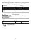
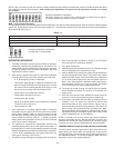
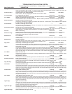
TABLE 13. - MCB/FCB Dipswitches:
Dipswitch Function Switch Position
Hot Water Boilers Hydronic Heating Boiler
Switch 1: Selection of the type of boiler application: On = VW Off = VB
Switch 2: Trials for ignition: On = 3 Off = 1
Switch 3: IRI Gas Valve Not Available:
Switch4:ControllingProbe: On=Tank(Remote) Off=Inlet
Switch 5: Powered Venter: On = Yes Off = No
Switch6:LowWaterCutOff:(LWCO) On=Yes Off=No
Switch 7: Low Gas Pressure On = Yes Off = No
Switch 8: Modulation: On


Find Your Products By Category
Please Login
