
5.0
Owner's of the A.O. Smith Boiler VB/VW- 1000 gave it a score of 5.0 out of 5. Here's how the scores stacked up:
8
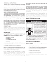
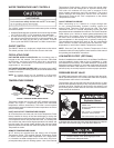
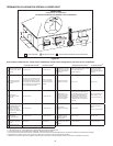
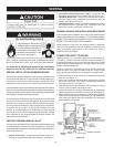
THE CONTROL SYSTEM
The control system consists of four basic components:
1) Modulation Control Board (MCB); 2) Power Distribution
Board(PDB);3)VariableFrequencyDrive(VFD),seeFigure
2; User Interface Module, see Figure 20. The Modulation
Control Board and the Power Distribution Board are located
in the control box and can be accessed by opening the front
door of the unit. The User Interface Module is attached to
the front door panel. Every system will have one Modulation
ControlBoard(MCB), onePowerDistributionBoard(PDB),
andoneUserInterfaceModule(UIM).
TheMCBcontainsdipswitcheswhichareusedtocongurethe
boiler for several different control options, see the Control System
Section.
FIGURE 2.
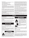
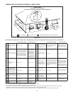
HOT SURFACE IGNITER
The Hot Surface Igniter is a device that ignites the main burner by high
temperature(>1800°F)[982°C],seeFigure3.Theigniterismade
of recrystallized silicon carbide, and when 120 VAC is applied to the
igniter,sufcientheatisgeneratedtoignitethemainburner.Although
improvements have been made to strength en the igniter, it is still fragile
and care must be taken in handling the igniter to prevent breakage.
FIGURE 3. FIGURE 4.
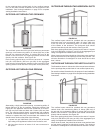
PRESSURE SWITCHES
This control system has 3 pressure switches that are standard. Blocked
InletPressureSwitch(BIS),BlowerProverSwitch(BPS)BlockedFlue
Switch(BFS).
The BPS on this model is a normally open switch that closes on increased
vacuum. Once the blower moves enough air to create a vacuum across
theVenturitheBPSisactivated.Iftheblowerfailsorcannotmovesufcient
air a soft lockout will occur. Inspect the blower for correct operation.
TheBlockedInletSwitch(BIS)willactivateistheintakeisblockedonly
during the heating cycle. The BIS is a normally closed pressure switch
that opens when the air intake is blocked. If the BIS is activated check
and clear the intake of any obstructions.
Theblockeduepressureswitch(BFS)activatedwhentheexhaust
ueoftheunitisrestrictedorblocked.TheBFSisanormallyclosed
switch that opens when positive pressure is placed on the switch
because of any restriction to the exhaust venting. If the BFS is
activated check and clear any obstructions causing the restriction.
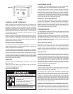
LOW GAS SWITCH
This VF boiler is available with a low gas pressure switch which
meets the CSD-1 code requirements, see Figure 5.
TheLowGasPressureSwitch(LGPS)isnormallyclosedandremains
closed unless the pressure falls below the preset pressure.
FIGURE 5.
LOW GAS PRESSURE SWITCH.
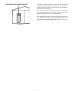
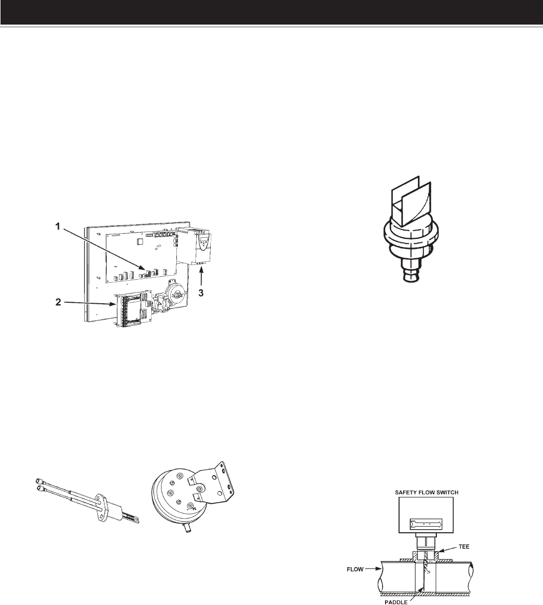
WATER FLOW SWITCH
The water ow switch is installed at the boiler outlet to
preventburneroperationintheeventofinadequatewaterow
through the boiler. It is a normally open switch that will close
itscontactswhenincreasingwaterowrateisdetected.The
waterowswitchisfactory-set.Thecontactswillopenwhen
theowratedropsbelowthefactorysettingcausingthegas
valve to close which will turn off the gas to the burner, see
Figure 6. Under no circumstances shall the ow switch be
tampered with or bypassed. Doing so may cause damage to
the heat exchanger not covered under the warranty.
FIGURE 6. WATER FLOW SWITCH.
FLAME SENSOR
EachBoilerisequippedwithtwoamesenorscoupledtogether
todetectthepresenceoftheburneramesathighandlowre
conditions.Theseamesensorsworktogetherasonetosense
theflame.Ifnoflame issensed,thegasvalve(s)willclose
automatically.Ifnoameissensedonthreeignitiontrials,theboiler
will lock out. In the event of a lockout, depress the SELECT button
on the display board to restart the boiler.
CONTROL COMPONENTS


Find Your Products By Category
Please Login
