
5.0
Owner's of the A.O. Smith Boiler VB/VW- 1000 gave it a score of 5.0 out of 5. Here's how the scores stacked up:
12
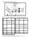
fortheopeningsthatprovidefreshairintoconnedspaces
only. Do not refer to these illustrations for the purpose of vent
installation. See Venting Installation on page 18 for complete
venting installation instructions.
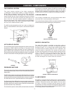
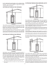
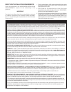
OUTDOOR AIR THROUGH TWO OPENINGS
FIGURE 9A.
The confined space should be provided with two permanent
openings,onecommencingwithin12inches(300mm)ofthe
topandonecommencingwithin12inches(300mm)ofthe
bottom of the enclosure. The openings should communicate
directly with the outdoors. See Figure 9A.
Each opening should have a minimum free area of 1 square
inchper4,000Btu/hr(550mm
2
perkW)oftheaggregate
input rating of all appliances installed in the enclosure. Each
openingshouldnotbelessthan100squareinches(645cm2).
OUTDOOR AIR THROUGH ONE OPENING
FIGURE 9B.
Alternatively a single permanent opening, commencing within 12
inches(300mm)of topofenclosure,shouldbeprovided.See
Figure 9B. The appliance should have clearances of at least 1
inch(25mm)fromsidesandbackand6inches(150mm)from
front. The opening should directly communicate with outdoors
or should communicate through a vertical or horizontal duct to
outdoors or spaces that freely communicate with outdoors and
should have a minimum free area of the following:
1. 1squareinchper3000Btu/hr(700mm
2
perkW)ofthetotal
input rating of all appliances located in the enclosure, and
2. Not less than the sum of areas of all vent connectors in
the space.
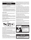
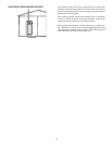
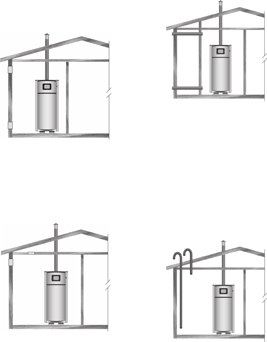
OUTDOOR AIR THROUGH TWO HORIZONTAL DUCTS
FIGURE 9C.
The conned space should be provided with two permanent
horizontal ducts, one commencing within 12 inches (300 mm)
of the top and one commencing within 12 inches (300 mm)
of the bottom of the enclosure. The horizontal ducts should
communicate directly with the outdoors. See Figure 9C.
Each duct opening should have a minimum free area of 1 square
inchper2,000Btu/hr(1100mm
2
perkW)oftheaggregateinput
rating of all appliances installed in the enclosure.
When ducts are used, they should be of the same cross sectional
area as the free area of the openings to which they connect. The
minimum dimension of rectangular air ducts should be not less
than 3 inches.
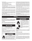
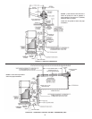
OUTDOOR AIR THROUGH TWO VERTICAL DUCTS
The illustrations shown in this section of the manual are a reference
fortheopeningsthatprovidefreshairintoconnedspacesonly.
Do not refer to these illustrations for the purpose of vent installation.
See Venting Installation on page 19 for complete venting installation
instructions.
FIGURE 9D.
The conned space should be provided with two permanent
vertical ducts, onecommencing within 12 inches(300 mm) of
thetopandonecommencingwithin12inches(300mm)ofthe
bottom of the enclosure. The vertical ducts should communicate
directly with the outdoors. See Figure 9D.
Each duct opening should have a minimum free area of 1 square
inchper4,000Btu/hr(550mm
2
perkW)oftheaggregateinput
rating of all appliances installed in the enclosure.
When ducts are used, they should be of same cross sectional area
as free area of openings to which they connect. The minimum
dimension of rectangular air ducts should be not less than 3 inches.


Find Your Products By Category
Please Login
