

5.0
Owner's of the A.O. Smith Boiler VB/VW- 1000 gave it a score of 5.0 out of 5. Here's how the scores stacked up:
33
OPERATION
IMPORTANT
Onlyqualiedpersonnelshallperformtheinitialringoftheboiler.
At this time the user should not hesitate to ask the service agent
any questions regarding the operation and maintenance of the unit.
If you still have questions, please contact the factory or your local
A.O. Smith representative.
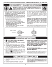
Lighting and Operating instructions are included with this manual.
By using these instructions, the user may be able to make minor
operational adjustments and save unnecessary service calls.
However the user should not attempt repairs, but should contact
a service technician or gas supplier.
GENERAL
Neveroperatetheboilerwithoutrstmakingsuretheboilerand
systemarelledwithwater,inaddition:
For hot water supply installations:
• Makesureatemperatureandpressurereliefvalveisinstalledat
the boiler and, if used, the storage tank. Also check for leaks.
For heating boiler installations:
• Makesurethattheboilerandsystemhavebeenpurgedofair
and checked for leaks.
Also be sure to check the gas piping for leaks before beginning the
initialringoftheboiler.
FILLING AND PURGING OF HEATING BOILER
INSTALLATION
1. Fastllsystemthroughbypassuntilpressureapproaches
desired system pressure. Close bypass valve and permit
pressure to be established by the pressure reducing valve.
2. Vent all high points in system to purge system of air.
Provisions should be made to permit manual venting of radiators
or convectors.
FILLING HOT WATER SUPPLY BOILER
INSTALLATION
1. Close the system’s drain valve by turning handle clockwise.
2. Open a nearby hot water faucet to permit the air to escape.
3. Fully open the cold water inlet pipe valve allowing the boiler
andpipingtobelled.
4. Closethehotwaterfaucetaswaterstartstoow.
5. The boiler is ready to be operated.
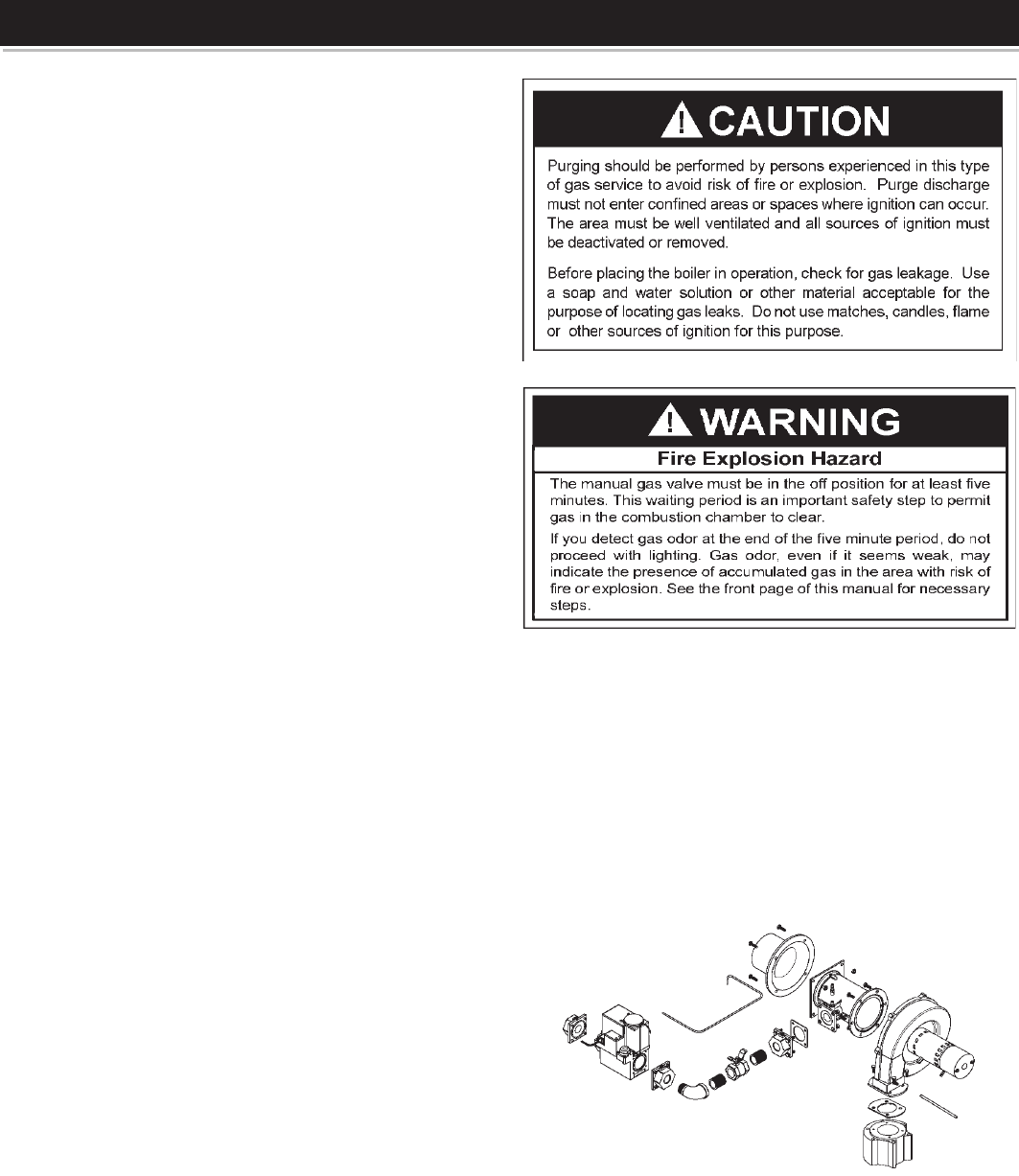
PURGING GAS LINE
Gas line purging is required with new piping or systems in which
air has entered.
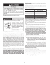
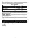
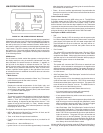
INLET GAS PRESSURE
Theinletgaspressureismeasuredbyremovingthe1/8”NPTPlug
located on the main gas manifold which is upstream of the unit’s gas
valve,andinserta1/8”NPThosebarbttingtobeconnectedtoa
manometer or pressure gauge. Once pressure has been checked and/
or adjusted, replace the plug and check for leaks. The maximum value
speciedinthetablemustnotbeexceeded.Theminimumvalues,
shown in Table 1, must be maintained under both load and no load
conditions(staticandringconditions).Thecombinationgasvalves
supplied with the boiler are for low pressure service. If upstream
pressure exceeds 14.0” W.C., an intermediate gas pressure
regulator of the lockup type must be installed.
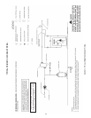
FIGURE 19. GAS TRAIN ASSEMBLY.


Find Your Products By Category
Please Login
