

5.0
Owner's of the A.O. Smith Boiler VB/VW- 1000 gave it a score of 5.0 out of 5. Here's how the scores stacked up:
24
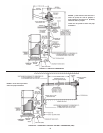
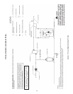
This is accomplished by changing two dipswitch settings on the
MCB.First,dipswitch“4”mustbesettothe“ON”positionto
designate the remote probe as the controlling probe. Second,
dipswitch “1” must be set to the “OFF” position to limit the
maximum remote probe temperature for VW applications. Also,
makesuredipswitch“1”issettothe“OFF”position,whichsets
the outlet temperature for VW applications. Failure to do this
will void the warranty. If the remote probe is not designated
as the controlling probe, the unit will be controlled by the inlet
probe and will not use the desired tank temperature as its base.
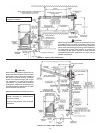
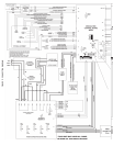
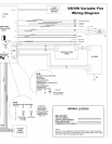
Refer to Connection Diagram, Figure 17, in order to connect
the remote probe to the boiler, see Tables 9, 10, 13 and 14
for Dipswitch positions.
GAS CONNECTIONS
Make sure the gas on which the boiler is to operate is the
same as that specified on the rating plate. Do not install
the boiler if equipped for a different type of gas. Consult
your gas supplier.
This boiler is not intended to operate at gas supply pressure
other than shown on the rating plate. A lock-up or positive
shut-off type regulator must be installed in the gas supply
line. Exposure to higher gas supply pressure may cause
damage to gas valves which can result in fire or explosion.
If overpressure has occurred such as through improper
testing of gas lines or emergency malfunction of the supply
system, the gas valves must be checked for safe operation.
Make sure that the outside vents on the supply regulators
and the safety vent valves are protected against blockage.
These are parts of the gas supply system, not the boiler.
Vent blockage may occur during ice build-up or snowstorms.
The boiler must be isolated from the gas supply piping
system by closing its main manual gas shut-off valve during
any pressure testing of the gas supply piping system at
test pressures equal to or less than 1/2 psig.
Disconnect the boiler and its main manual gas shut-off valve
from the gas supply piping during any pressure testing of the
gas supply system over 1/2 psig. The gas supply line must be
capped when not connected to the boiler.
It is important to guard against gas valve fouling from
contaminants in the gas ways. Such fouling may cause
improper operation, fire or explosion. If copper supply
lines are used they must be approved for gas service.
When local codes require a main manual shut-off valve
outside the boiler jacket, a suitable main manual shut-off valve
must be installed in a location complying with those codes.
Before attaching the gas line be sure that all gas pipe is clean on
the inside.
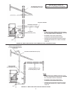
To trap any dirt or foreign material in the gas supply line, a
dripleg(sedimenttrap)mustbeincorporatedinthepiping.The
drip leg must be readily accessible and not subject to freezing
conditions. Install in accordance with recommendations of serving
gas supplier. Refer to the current edition of the national fuel gas
code, ANSI Z223.1 or CAN/CSA – B149.1, and current addenda.
Size of gas supply piping may be larger than heater connection on
installationswhereasignicantrunofpipingisrequired.
To prevent damage, care must be taken not to apply too much
torque when attaching gas supply pipe to boiler gas inlet.
Fittings and unions in the gas line must be of the metal to metal type.
Applyjointcompounds(pipedope)sparinglyandonlytothemale
threadsofpipejoints.Donotapplycompoundtothersttwothreads.
Usecompoundsresistanttotheactionofliqueedpetroleumgases.
GAS SUPPLY LINE SIZING
The gas piping installation must be capable of supplying the
maximum probable gas demand without excessive pressure loss.
Depending on local practices, the ALLOWABLE PRESSURE
LOSS between the gas meter, or service regulator and each
applianceisgenerally0.3or0.5inchesofwatercolumn(0.075
or0.124kPa).
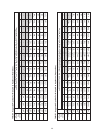
For single boiler installation, refer to Table 5 for appropriate pipe
length for the appliance maximum rate.
For multiple boilers refer to Table 6 for natural gas and Table 7 for
propane. Maximum pressure drop is 0.5 for these charts.
Reference tables are from ANSI Z223.1 National Fuel Gas Code or
CAN/CSA-B149.1-00(andcurrentaddenda):
Natural gas is 1000 BTU/ft^
3
@0.6specicgravity
Propane gas is 2500 BTU/ft^
3
@1.5specicgravity
< pipe length longer than 200 feet consult applicable codes
No additional allowance is necessary for an ordinary number of
ttings.Whereitisnecessarytousemorethantheaveragenumber
ofttings(i.e.,elbows,teesandvalvesingassupplyline)useapipe
largerthanspeciedtocompensateforincreasedpressuredrop.
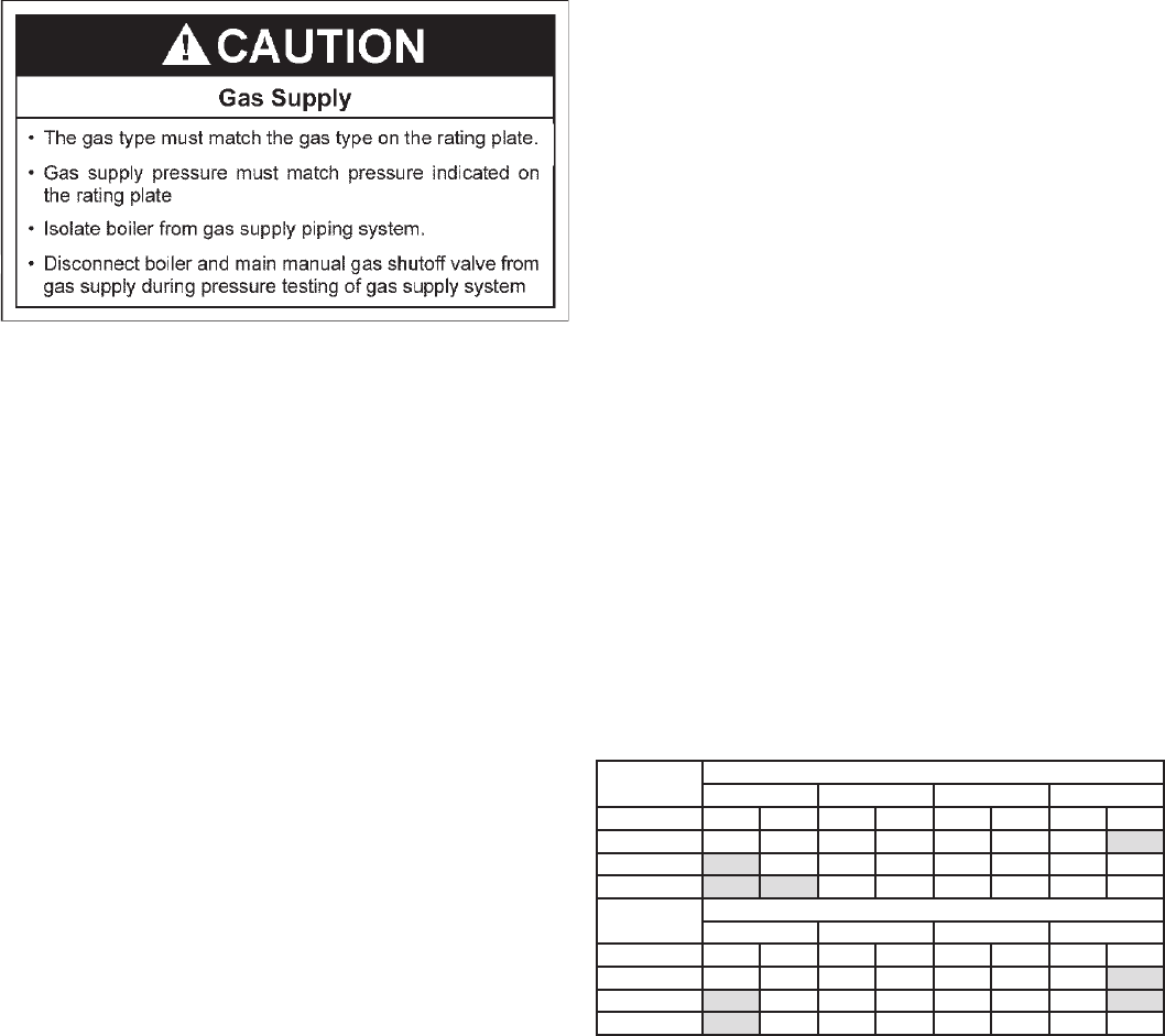
TABLE 5.
SINGLE UNIT INSTALLATION, SUGGESTED GAS PIPE SIZING.
MAXIMUM EQUIVALENT PIPE LENGTH (IN FEET).
Nom. Pipe
0.3 in w.c. drop
1” 1.25” 1.5” 2”
BTU input Nat Prop Nat Prop Nat Prop Nat Prop
500,000 10 25 40 90 80 200 200
750,000 10 10 40 40 90 125 <
1,000,000 10 20 20 50 70 175
Nom. Pipe
0.5 in w.c. drop
1” 1.25” 1.5” 2”
BTU input Nat Prop Nat Prop Nat Prop Nat Prop
500,000 10 40 60 150 150 200 <
750,000 10 30 70 70 150 200
1,000,000 10 10 40 30 90 125 <


Find Your Products By Category
Please Login
