

5.0
Owner's of the A.O. Smith Boiler VB/VW- 1000 gave it a score of 5.0 out of 5. Here's how the scores stacked up:

6
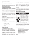
This design complies with the current edition of the ANSI
Z21.13 low-pressure boiler standard.
Compliance under this standard implies that when the boiler
underwent test, the gas manifold and control assembly pro vided
on the boiler met safe lighting and other performance criteria.
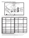
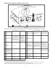
Detailed installation diagrams are found in this manual. These
diagrams will serve to provide the installer a reference for the
materials and methods of piping necessary. It is essential that
all water, gas piping and wiring be installed as shown on the
diagrams. You should thoroughly read and understand this
manual before installation and/or operation of this boiler.
The factory warranty will be void if the boiler(s) have been
improperly installed or operated.
AL 29-4C
®
is a registered trademark of Allegheny Ludlum
Corporation.
Inadditiontotheseinstructions,theboiler(s)shallbeinstalledin
accordance with those installation regulations in force in the local
area where the installation is to be made. These shall be carefully
followed in all cases. Authorities having jurisdiction should be
consulted before installations are made.
In the absence of local codes, the installation must comply with
the current editions, as follows:
In the United States:
The National Fuel Gas Code, ANSI Z223.1/NFPA 54 and the
National Electric Code, NFPA 70.
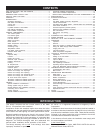
CONTENTS
INTRODUCTION
SAFE INSTALLATION, USE AND SERVICE ...........................................2
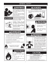
GENERAL SAFETY......................................................................................3
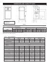
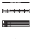
DIMENSION AND CAPACITY DATA .........................................................4
CAPACITY AND FLOW DATA ....................................................................5
CONTENTS ...................................................................................................6
INTRODUCTION ...........................................................................................6
Grounding Instructions ............................................................................. 7
Inlet Water Considerations ......................................................................7
Correct Gas .............................................................................................. 7
Precautions ...............................................................................................7
Liqueed Petroleum Gas Models ..........................................................7
High Altitude Installations ........................................................................ 7
Field Installed Components ....................................................................7
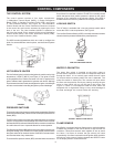
CONTROL COMPONENTS ......................................................................... 8
The Control System ................................................................................8
Hot Surface Igniter ..................................................................................8
Pressure Switches ...................................................................................8
Low Gas Switch ......................................................................................8
Water Flow Switch ..................................................................................8
Flame Sensor ........................................................................................... 8
Water Temperature Limit Controls ......................................................... 9
ON/OFF Switch ........................................................................................ 9
Circulating Pump ......................................................................................9
Temperature Probes ................................................................................9
Low Water Cutoff (Optional) ..................................................................9
Pressure Relief Valve ..............................................................................9
GENERAL .................................................................................................... 10
Required Ability ......................................................................................10
Location ................................................................................................... 10
Panels and Covers ................................................................................10
Chemical Vapor Corrosion ....................................................................11
Installtion Clearances .............................................................................11
Leveling ................................................................................................... 11
Air Requirements ...................................................................................11
Unconned Space ..................................................................................11
Conned Space .....................................................................................11
Fresh Air Openings for Conned Spaces ..........................................11
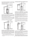
Outdoor Air Through Two Openings ................................................... 12
Outdoor Air Through One Opening ....................................................12
Outdoor Air Through Two Horizontal Ducts .......................................12
Outdoor Air Through Two Vertical Ducts ...........................................12
Air From Other Indoor Spaces............................................................13
Termination Clearances Sidewall Power Vent ...................................14
Termination Clearances Sidewall Direct Vent ....................................15
VENTING .....................................................................................................16
Special Installation Considerations .......................................................16
Venting System Using AL 29-4C
®
....................................................... 16
General Exhaust Vent Installation Procedure ....................................16
Connecting Vent to Boiler ....................................................................16
Venting Supports ....................................................................................17
Vertical Installation Requirements ........................................................17
Horizontal Installtion Requirements ...................................................... 17
Direct Vent Installation Requirements .................................................19
INSTALLATION REQUIREMENTS FOR THE COMMONWEALTH OF
MASSACHUSETTS .....................................................................................19
SYSTEM INSTALLATION ..........................................................................22
General ....................................................................................................22
Hot Water Heating (Hydronic) Equipment .......................................... 22
Internal Contaminants ............................................................................ 23
Hot Water Supply Boiler System - General Water Line Connections ... 23
Hard Water Conditions ..........................................................................23
Thermal Expansion (Closed System) ..................................................23
Remote Probe Installation Procedure .................................................23
Gas Connections ...................................................................................24
Gas Supply Line Sizing ........................................................................24
Wiring ......................................................................................................28
SUGGESTED PIPE SIZING TABLES .....................................................29
WIRING DIAGRAM ....................................................................................30
VB/VW-500, 750 & 1000 SCHEMATIC DIAGRAM ...............................32
OPERATION ................................................................................................ 33
Important .................................................................................................33
General ....................................................................................................33
Filling and Purging of Heating Boiler Installation..............................33
Filling Hot Water Supply Boiler Installation .......................................33
Purging Gas Line ..................................................................................33
Inlet Gas Pressure ................................................................................33
Water Temperature Regulation ............................................................. 34
LIGHTING & OPERATION INSTRUCTIONS ..........................................36
Adjustment ..............................................................................................37
Setting of the Test Mode .....................................................................37
Control System .......................................................................................37
Inputs to MCB .......................................................................................38
Operating Sequence .............................................................................. 39
UIM Operating Procedures ................................................................... 40
Operating Setpoint Adjustment Procedure ..........................................41
High Limit Differential Setpoint Adjustment Procedure .....................42
TROUBLESHOOTING IGNITION SYSTEM ............................................44
Troubleshooting Gas Valve ...................................................................45
Main Burner ............................................................................................45
PREVENTATIVE MAINTENANCE ............................................................. 45
Relief Valve ............................................................................................46
Combustion Air Filter .............................................................................46
Blower Compartment .............................................................................46
Burner Maintenance ...............................................................................46
Condensate Removal System .............................................................. 46
Venting Maintenance .............................................................................47
Heat Exchanger Preventative Maintenance ........................................47
Deliming ..................................................................................................47
Tube Cleaning Procedure Mechanical Removal of Deposits ..........47
Replacement Parts ................................................................................47
NOTES ......................................................................................................... 48
LIMITED WARRANTY ................................................................................ 51


Find Your Products By Category
Please Login
