
5.0
Owner's of the A.O. Smith Boiler VB/VW- 1000 gave it a score of 5.0 out of 5. Here's how the scores stacked up:
39
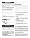
NOTE: If the unit powers up with the number of stages selected by dip switches exceeding the number of FCBs, the MCB will detect
this condition and go into a hard lockout. After changing the dipswitches, the power must be cycled off and back on to accept
any changes.
ExampleofDipswitchconguration:
VB model, 1ignition trial, not used, tank / remote probe, no power vent, No LWCO,
no low gas pressure, modulation, not used, not used.
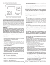
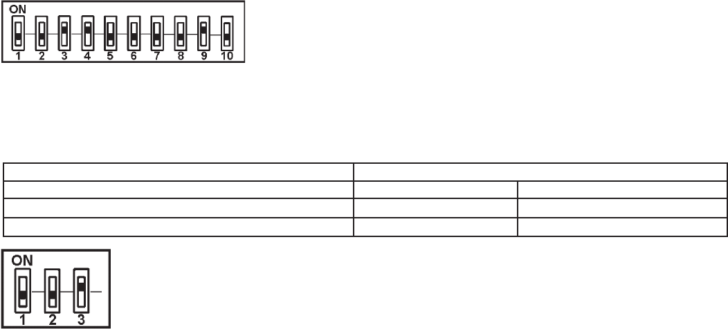
MCB - Three position Dipswitch:
This dipswitch is similar to the MCB dipswitches described above, but with only three switches being used: the number of blower speeds
(switch#3),HiGasoption(switch#2)andaspare(switch#1).OnlytheblowerspeedandHiGasoptionsaretherequiredselection,
within the MCB, see Figure 17.
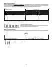
TABLE 14.
Dipswitch Function: Dipswitch Position
Switch 1: Spare:
Switch 2: Hi Gas pressure switch: On = Yes Off = No
Switch 3: Number of Blower Speeds: On = 1 speed, Off = 2 speed
ExampleofDipswitchconguration:
No High Gas, 1 blower speed..
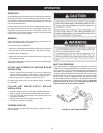
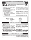
OPERATING SEQUENCE
1. The EMC modulation controller has four modes of operation:
Initialization, Standby, Running/Modulation, and Service. The
internal MCB micros control these modes through a sequence
ofsteps(orStates)whicharefurtherdescribedinthe“UIM
OperatingProcedures”section.
2. When power is applied to the system, it enters the initialization
mode and the following automatic functions are performed:
• A.O.Smithopeningscreenisdisplayed.
• Thesystemgoesthroughacalibrationindicatedbythe
green running LED blinking and then staying on; next the
red service LED and yellow standby LEDs come on, next
the service and runnings LEDs blink ON and OFF.
• Storedvaluesarerecalledfrommemory.
• Congurationdipswitchesareread.
• Pendingfaultsarerecalled
• Microsonallboardsstartrunning(indicatedbyaashing
YellowLEDneareachmicro)
• Inputsensorsareread
3. Afterinitializationiscomplete(approximately10seconds)
the system turns the green LED off and goes to the standby
mode(yellow“Standby”LEDon),unlessapreviouslystored
fault has been recalled, which will send the system into the
servicemodel(red“Service”LEDon).Instandbymodethe
display shows the temperature screen and in fault mode the
current error screen is displayed.
4. The system then compares the temperature read from the
controllingprobe(inletortank)tothesetpointtemperature.If
the temperature is less than the operating setpoint minus the
differential temperature and the thermostat input is closed then
a call for heat is established and the system shifts to the run
mode(green“Running”LEDturnson).
5. The heating sequence begins by applying power to the pump.
6. After a few seconds the blower is turned on for 30-second
pre-purge period of combustion chamber.
7. The igniter is turned on.
8. After the igniter has reached a minimum of 2.8 amps, the gas
valveisenergizedtoallowgasowtoburner.
9. After an additional one second, the system checks the status of
theamethroughtheamesensor.Iftheameisnotveried
within 4 seconds, the gas valve is immediately shut off followed
by 15-second inter-purge period, then the system returns to
step7,ifthe“TrialforIgnition”dipswitchissetforthree(3)tries.
Ifthedipswitchissetforone(1)trial,thesystemwilldeclare
an error and boiler will require resetting the control.
10. Theboilerwillremainrunninguntilthesetpointissatised.
Oncesatised,theblowerwillcontinuefor15-secondpost
purge period.
11. Oncesetpointhashavebeensatised,theboilerpumpwill
continue to run for the programmed post-circulate cycle.
12. The control now enters the idle state as displayed by the
“Standby”LED.Thecontrolwillcontinuetomonitorheat
demand and state of other system devices. Upon a drop of
water temperature below the set parameters, the control will
return to step 5 and repeat the entire operating cycle. Note:
Any fault detection, during standby or running modes, will halt
the heating sequence and shift the system to the service mode
where the detected fault will be displayed.
NOTE: In standby and running modes the system constantly
monitors the signals and the internal operation for faults. Any
detected fault will halt the heating sequence and shift the system
to the service mode, where the detected fault will be displayed.
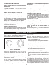
TEMPERATURE SETPOINTS (SYSTEM CONTROL ALGORITHM)
The boiler has a hysteresis type control, which means that it will
begin heating the water when the temperature sensed by the
controlprobe(inletortank)fallsbelowtheoperatingsetpointminus
the differential setpoint. It will stop heating the water when the
temperature rises to the operating setpoint.


Find Your Products By Category
Please Login
