

5.0
Owner's of the A.O. Smith Boiler VB/VW- 1000 gave it a score of 5.0 out of 5. Here's how the scores stacked up:
23
7. SYSTEM CONTROLLER
Controlling of these systems is decided mainly by the type
of building system controlling desired. A single boiler
installation might be controlled directly from space
temperaturethermostat(s).Multipleboilerinstallationsare
more effective when the boilers are sequenced in and out of
operation by some form of main water temperature controller.
With one or two boilers, individual control settings at
progressive temperature may be used. For more than
two boilers, electronic sequencing controlling is
recommended. Individual controls, or the separate stages
of a step controller, should start the boiler loop circulator
and fire the boiler. Some large installations may require the
firing of more than one boiler per stage.
The system or primary circulator may or may not be
controlled by the boiler sequencer. When this pump is
operated through the first switch of any type of step
controller, care should be taken to determine if a motor
starter is needed due to insufficient switch capacity.
Multiple boiler installations are especially adapted to the
use of outdoor reset for main water temperatures. This
feature is not mandatory, but offers smooth, efficient
operation of a modern system.
Normal use of flow control valves is required to prevent
cross circulation of zones as with any multiple pump system.
Large systems with multiple boilers should include main
water temperature controls (with or without outdoor
reset) tosequence theboiler onand off, inrelation to
the load on the system.
24VAC System Controller (Optional) - VB models require
a field supplied 24VAC operating control to be installed in
the system such as: loop thermostat, indoor/outdoor reset
control, sequencing panel, or energy management system.
The connection for such devices is located in the junction
box at the rear of the unit. A 24VAC thermostat/aquastat can
onlybeusedasan“On/Off”switchfortheunit.Theactual
controlling of the phasing will be through either the inlet or
remote probe. To use a 24VAC system controller, dipswitch
“4”ontheMCBmustbeswitchedtothe“on”position,see
REMOTE PROBE INSTALLATION.
INTERNAL CONTAMINANTS
The hydronic system must be internally cleaned and flushed
after a new or replacement boiler has been installed, to
remove contaminants that may have accumulated during
installation. This is extremely important when a replacement
boiler is installed into an existing system where Stop Leak
or other boiler additives have been used.
Failure to clean and flush the system can produce acid
concentrations that become corrosive, and leads to heat
exchanger failure.
All hot water heating systems should be completely flushed
with a grease removing solution to assure trouble-free opera-
tion. Pipe joint compounds, soldering paste, grease on tubing
and pipe all tend to contaminate a system
Failure to flush contaminants from a system can cause solids
to form on the inside of boiler exchangers, create excessive
blockage of water circulation, deterioration of the pumps seal
and impellers.
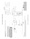
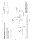
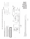
HOT WATER SUPPLY BOILER SYSTEM - GENERAL
WATER LINE CONNECTIONS
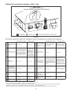
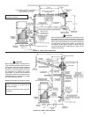
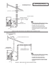
This section provides detailed installation diagrams for a
typical method of application for the unit.
Piping diagrams will serve to provide the installer with
a reference for the materials and methods of piping
necessary for installation. It is essential that all water
piping be installed and connected as shown on the
diagrams. Check the diagrams to be used thoroughly
before starting installation to avoid possible errors and to
minimize time and material cost.
It is essential that all water piping be installed and
connected as shown on the diagrams. Check the diagrams
to be used thoroughly before starting installation to avoid
possible errors and to minimize the time and material cost.
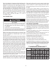
HARD WATER CONDITIONS
Where hard water conditions exist, water softening or the
threshold type of water treatment is recommended. This
will protect the dishwashers, coffee urns, water heaters,
water piping and other equipment. When water softening
or water treatment is not practical, a comparatively easy
method of periodic lime removal from the unit may be
employed.
SHUTOFF VALVES SHOULD BE INSTALLED FOR
SERVICING BOILER, HOWEVER, LOCAL CODES SHALL
GOVERN THEIR USAGE.
THERMAL EXPANSION (CLOSED SYSTEM)
As water is heated, it expands (thermal expansion). In
a closed system the volume of water will grow when it is
heated. As the volume of water grows there will be a
corresponding increase in water pressure due to thermal
expansion. Thermal expansion can cause premature tank
failure(leakage).Thistypeoffailureisnotcoveredunder
the limited warranty. Thermal expansion can also cause
intermittent Temperature-Pressure Relief Valve operation:
water discharged from the valve due to excessive pressure
build up. This condition is not covered under the limited
warranty. The Temperature-Pressure Relief Valve is not
intended for the constant relief of thermal expansion.
A properly sized thermal expansion tank must be installed on
all closed systems to control the harmful effects of thermal
expansion. Contact a local plumbing service agency to have
a thermal expansion tank installed.
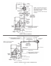
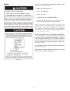
REMOTE PROBE INSTALLATION PROCEDURE
A remote probe is supplied with each hot water supply
boiler(VWmodels).Toconnecttheremoteprobetothe
boiler, remove the cover from the junction box at the rear
of the unit. Connect the probe wire pigtails, see Figure 7.
Check the field connection diagram located on this cover
of the junction box to assure proper wiring.
Once the remote probe has been connected to the boiler, it
must be designated as the controlling probe for the system.


Find Your Products By Category
Please Login
