

5.0
Owner's of the A.O. Smith Boiler VB/VW- 1000 gave it a score of 5.0 out of 5. Here's how the scores stacked up:

22
SYSTEM INSTALLATION
GENERAL
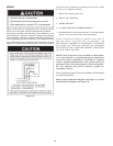
If the system is to be filled with water for testing or other
purposes during cold weather and before actual operation,
care must be taken to prevent a downdraft entering the boiler
or freezing air from contacting the system. Failure to do so
may cause the water in the system to freeze with resulting
damage to the system. DAMAGE DUE TO FREEZING IS
NOT COVERED BY THE WARRANTY.
Good practice requires that all heavy piping, etc., be support ed.
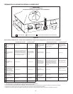
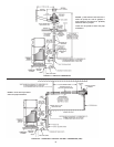
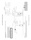
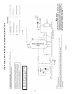
Figure 13 shows a typical primary, secondary piping method.
This is the preferred piping method for most copper fin tube
boilers. Other piping methods, however, may provide good
system operation. A prime concern when designing heating
systems is the maintenance of proper flow through the unit
during boiler operation. The secondary pump should be sized
per the recommended flow rate of the boiler, see Dimension
and Capacity Data in this manual.
A system bypass should be installed, as shown in Figure
13, to prevent boiler circulation starvation when the system
zones call for reduced flow.
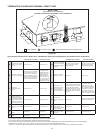
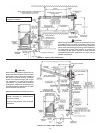
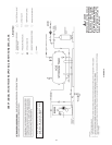
This bypass may also be used with multiple boilers manifolded
for reverse-return flow. This system bypass would be installed
from boiler outlet to suction side of pump.
HOT WATER HEATING (HYDRONIC) EQUIPMENT
The following is a brief description of the equipment required
for the installations noted in this manual. All installations
must comply with local code.
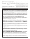
1. WATER SUPPLY LINE
These boilers can be used ONLY in a forced circulation
hot water heating system. Since most forced circulation
systems will be of the closed type, install the water supply
line as shown on piping diagram, see Figure 13.
Fast filling of large pipe, old radiator installations and
pressure purging of series loop systems (where high
pressures are not available) requires bypassing of the
pressure reducing valve.
Gener ally, pressure purging is not possible with a well
pump system. High point air venting is essential.
If the system is of the open type, a pressure reducing
valve will not be required as the water supply to the
system will be controlled by a manu ally operated valve.
An overhead surge tank is required. A minimum pressure
of 15 psi (100kPa)must be maintained on the boilerat
all times to ensure avoidance of potential damage to the
boiler which may not be covered by the warranty.
2. EXPANSION TANK
If the system is of the closed type, install an expansion
tank as shown in Figure 13. The sizing of the expansion
tank for a closed system is very important and is directly
related to the total water volume of the system. Refer
to “Systems and Equipment” volume of the ASHRAE
handbook.
An air separator as shown in the piping diagrams is recom-
mended especially for modern commercial hydronic systems.
3. VENT VALVES
It is recommended that automatic, loose key or screw-
driver type vent valves be installed at each convector
or radiator.
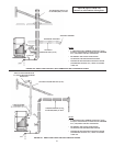
4. SYSTEM HEADERS
Split systems with individual supply and return lines from
the boiler room should normally have this piping connected
to supply and return manifold headers near the boiler. To
achieve good water distribution with maximum pressure
drop for sever al circuits, manifolds should be larger than
system mains.
The circuits should be spaced on the heater at a minimum
of3”(76mm)centertocenter.Installabalancingcockin
each return line.
Manifold headers are recommended for split systems
with or without zone valves and also those installations
with zone circulators. If the system is to be split at
remote points, good practice requires special attention
be given to main pipe sizing to allow balancing of water
flow.
5. COOLING PIPING
When the boiler is used in conjunction with a refrigeration
system it must be installed so that the chilled medium is
piped in parallel with the boiler. Appropriate flow control
valves, manual or motorized, must be provided to prevent
the chilled medium from entering the boiler.
Water temperature in the heating system must be reduced
tolessthan100°F(38°C)beforecoolingsystemisstarted,
or damage to the chiller unit may occur.
If the boiler is connected to chilled water piping or its
heating coils are exposed to refrigerated air, the boiler
piping system must be equipped with flow valves or other
automatic means to prevent gravity circulation through the
boiler during the cooling cycle.
Primary/secondary pumping of both the chiller(s) and
the boiler(s) is an excellent winter-summer change-over
method, because cooling flow rates are so much more
thanheatingflowrates.Inthiswayeachsystem(heating
orcooling) iscirculatedindependently.
6. CIRCULATING PUMP
FOR HOT WATER HEATING BOILERS - VB MODELS, the
circulatingpumpisNOTprovidedandmustbeeld-installed.
NOTE: If a system pump is to be installed on a VB
model, the maximum rating of the pump motor must
not exceed 1 hp.


Find Your Products By Category
Please Login
