
5.0
Owner's of the A.O. Smith Boiler VB/VW- 1000 gave it a score of 5.0 out of 5. Here's how the scores stacked up:
17
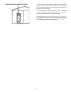
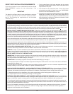
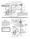
VENTING SUPPORTS
Care must be taken in the installation of the venting system that
adequate support is maintained throughout the installation process.
Whenextendingmorethan10feet(3.0m)vertically,verticalsupport
kitsarerequiredonceevery10feet(3.0m)ofverticalrun.Vertical
supportisalsorequiredimmediatelyafteranytransition(elbow,
tee,etc.)toverticalofover10feet(3.0m)ofrunandafterany
offset in the vertical run.
Thesupportbrackets(suppliedintheVerticalSupportKit)aretobe
secure ly fastened to a solid vertical member of the building using the
appropriate fasteners; i.e., wood screws for wood framing, machine or
tapping screws for structural steel or masonry anchors for solid masonry.
The bracket should be located so that it will not interfere with any joints of
the venting system. The bottom most support bracket should be located
directlyabovethersttransitionfromhorizontaltovertical,seeFigure
10. Refer to Figures 12, 12A, 12B and 12C.
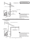
If a means of support for the brackets are not available and
horizontal vent sections are present, install hanger straps
(madefromnon-combustiblematerial)asclosetothepointsof
transition as possible. If the horizontal portions of the vent and/or
ventconnectorarelongerthan6feet(2.0m),theninstallhanger
strapsevery6feet(2.0m)tosupporttheconnector.
DO NOT rivet or screw the straps to the conduit or other wise
puncture the conduit wall. Instead, wrap an extra loop of strap
around the conduit to hold it in position, or attach the strap to
the center screw of the double wall AL 29-4C
®
vent coupling, if
applica ble.
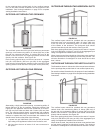
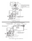
VERTICAL INSTALLATION REQUIREMENTS
1.The vent system must terminate at least 3 feet (1.0m)
andno morethan6feet (2.0m)abovetheroof lineand
no closer than 10 feet (3.0m) from any wall or vertical
structure. If the exhaust vent terminal is within 10 feet
(3.0m)ofawallorparapet,itmustextendaminimumof
2feet (610mm)abovethe wallorparapet, seeFigures
11 and 12A.
2. For direct vent installations, the total distance of the vent system
from the boiler vent connector to the vertical vent termination shall
notexceed70equivalentfeet(21.3m).Amaximumofthree90°
elbows can be used. Minimum vertical vent is 7 equivalent feet
(2.1m)fordirectventinstallations.Standardminimumverticalvent
lengthis7feet(2.1m),plusBoot-Tee.SeeFigures11,12A,12B,and
12C for differences between standard and direct vent installations.
3. An AL 29-C
®
Vent Vertical Vent Terminal must be used at
the termina tion.
4.Maintainaminimumof6feet(2.0m)separationbetween
the air intake and the exhaust terminals.
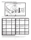
HORIZONTAL INSTALLTION REQUIREMENTS
1. The vent system must terminate with a AL 29-4C
®
Vent
Through-the-Wall Termination (TWT). Plan the terminal
location based on the dimensions shown in Figure 9. Do
not locatethe terminal within 8feet (2.5m) ofan inside
corner of a building or adjacent to outside walls, shrubs or
other such objects that may cause adverse wind conditions
in the immediate area.
2.TheTWTshallbelocatednotlessthan12inches(305mm)
above grade or, in geographical areas where snow
accumulates,nolessthan12inches(305mm)abovethe
antici pated snow line. Ensure that the TWT is protected
against blockage which may occur during ice build up or
snowstorms.
The TWT shall terminate at least 3 feet (1.0m) above
any forced airinlet within 10 feet(3.0m), except when
the forced air inlet is the combustion air intake of a
direct vent appliance. The TWT shall terminate at least
4feet (1.2m)below, 4feet(1.2m)horizontally fromor
1 foot (305mm) above any door, window or gravity air
inlet into any building as provided in the current edition
of the NATION AL FUEL GAS CODE ANSI Z223.1, see
Figure 9.
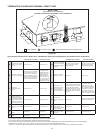
In addition, a minimum clearance of 4 feet (1.2m) hori-
zontally from, and in NO CASE ABOVE OR BELOW,
unless the 4 feet (1.2m) of horizontal distance is main-
tained from electric meters, gas meters, regulators and
relief equipment.
3. This horizontal exhaust vent system must pitch upward toward
theterminationat1/4inchperfoot(21mmpermeter).
4. The TWT is designed such that the building is protected
from degradation by flue gas and condensate. Howev er,
if additional protection is desired, install against the wall
a non-corrosive metal sheet under the TWT.
5. Due to the normal formation of water vapor in the combus-
tion process, horizon tal terminations must not be located
over areasof pedestrian orvehicular traffic,(i.e., public
walkways or over areas where condensate could create
a nuisance or hazard). This is especially true in colder
climates where ice buildup is likely to occur. A.O. Smith
Corporation will not be held liable for any personal injury
or property damage due to any dislodg ing of ice.


Find Your Products By Category
Please Login
