

5.0
Owner's of the A.O. Smith Boiler VB/VW- 1000 gave it a score of 5.0 out of 5. Here's how the scores stacked up:
37
ADJUSTMENT
Theremustbesufcientloadtooperatetheboilerathighreto
perform the following adjustments. Start the boiler and observe
proper operating parameters for the system.
Required Tools:
TORX
®
T40 or 5mm hex wrench
3mm or 7/64in hex wrench
Combustion analyzer
The VF 500, 750, and 1000 boilers are equipped with a Honeywell
combined gas/air control and gas safety shut off control valves. The
valve functions in parallel with the variable speed combustion blower to
supplythecorrectgasairratioforoptimumperformanceandefciency.
The combustion blower speed is controlled automatically and determines
the amount of negative pressure experienced by the gas safety shut off/
controlvalves.Thegas/airregulatoradjustsgasowtomaintaintheproper
pressure at the outlet nozzle of the associated valve.
SETTING OF THE TEST MODE
On UIM go to main menu, scroll down to user settings and press select.
Scroll down to MOD mode, press select. Use the up and down keys
toselectoptions:MIN(MINIMUMFIRINGRATE).MAX(MAXIMUM
FIRINGRATE).MOD(FORAUTOMATICMODULATIONMODE).
Press select for the desired option. For checking the combustion setup
on MIN or MAX the boiler will remain in this state for ten minutes before
defaultingtotheMOD(modulation)mode.
TABLE 11. - HIGH FIRE SETTING
NATURAL GAS 8.5 - 9.0% CO
2
PROPANE 9.5 - 10.5% CO
2
Set boilertothe “Test ModeHigh,”as describedabove, to
achieve maximum firing rate of the boiler. Check combustion
readings using a combustion analyzer. If combustion readings
are not in accordance with the chart above adjust as follows:
remove the flat, round, blue plastic cap from the cover.
Usinga3mm(7/64”)hexwrench,turntheadjustmentscrew
counterclockwise to increase or clockwise to decrease gas flow
and achieve the desired CO
2
level. See Table referenced above
for correct settings. There will be a slight time delay between
the adjustment and the response of the CO
2
measuring
instrument. Adjust the settings in small increments and allow
the combustion readings to stabilize before readjusting. When
desired adjustments are complete, reinstall the blue plastic cap
on the cover. Combustion samples shall be taken within two
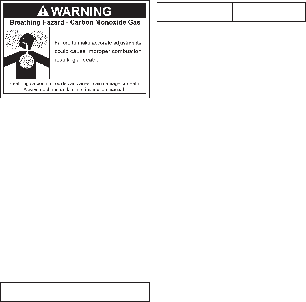
feet of the boiler. IMPROPER ADJUSTMENT CAN CAUSE
INCOMPLETE COMBUSTION RESULTING IN DEATH.
TABLE 12. - LOW FIRE SETTING
NATURAL 6.5 - 7.5% CO
2
PROPANE 7.5 - 8.5% CO
2
Set boiler to the “Test Mode Low,” as described above, to
achieve minimum firing rate of the boiler. Check combustion
readings using a combustion analyzer. If combustion readings
are not in accordance with the chart shown above adjust as
follows: remove the cap on the gas regulator using a slotted
screwdriver. This will expose the offset adjustment screw.
Using a TORX
®
T40 or a 5mm hex wrench, carefully adjust
the low fire gas setting to achieve the CO
2
level prescribed
in above reference table. Note: The rotation of the Low
Fire adjustment is opposite of the High Fire as follows:
Clockwise rotation increases gas flow, counterclockwise
rotation decreases gas flow.
Adjustments to the offset pressure regulators should not exceed 1/4
turn at a time before allowing the readings to respond and stabilize.
Afterproperlowreoffsetadjustmentismade,reinstalltheslotted
cap on the regulator.
Following all gas valve adjustments, check for proper light-off and
verify correct fuel/air mix and combustion quality throughout the
entireringrange(fromlowesttohighestfanspeed).
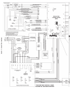
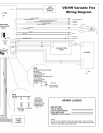
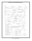
CONTROL SYSTEM
The EMC modulation control system is a fully integrated, state
of the art electronic control system. It consists of sensors, output
devices, a power switch, a 24VAC transformer, wiring, and the
following printed circuit boards:
• ModulationControlBoard(MCB),seeFigure2.
• PowerDistributionBoard(PDB),seeFigure2.
• UserInterfaceModule(UIM),seeFigure20.
TheMCBcontainscircuitryforbothmastercontroland ame
control. Dip switches on the MCB are used to configure the
system.TheUserInterfaceModule(UIM)communicateswiththe
user through a set of touch pads and a 4-line, 20-character LCD
display. The PDB provides connection points for input power, the
water pump, and the transformer. It also distributes power to the
system and contains the system fuses.
The MCB also contains an external communications system
to allow for connection to a PC, a modem, an EMS system,
or something similar. Through this connection, multiple
boilers can also be linked together. CAUTION: The internal
communications cables should never be connected to
the external communications connectors, and vice-
versa.
There are several microcontrollers used on the boards.
These control the temperature and ignition control functions
for the boiler. Inherent in the design are the normal operating
sequences and safety features associated with a gas ignition
control system. The system continuously performs various
diagnostic tests to verify proper appliance and control
operation. Should an unsafe condition occur, the control
will shut down the burner and display a red service light as
well as indicate the cause of the error on the display. The
operating programs for the system are stored in permanent
memory inside the microcontrollers. User-selectable
operating parameters and a history of detected faults are
stored in rewritable memory in the microcontrollers. A loss
of power does not affect either of the memories.


Find Your Products By Category
Please Login
