
5.0
Owner's of the A.O. Smith Boiler VB/VW- 1000 gave it a score of 5.0 out of 5. Here's how the scores stacked up:
40
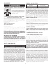
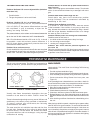
UIM OPERATING PROCEDURES
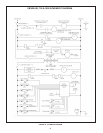
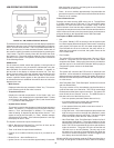
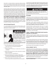
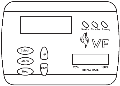
FIGURE 20. UIM, USER INTERFACE MODULE
The UIM receives commands from the user and displays operational
informationtotheuserviaanLCD(liquidcrystaldisplay)uptoeleven
LED’s,andvetouchswitches.TheLCDprovidesinformationto
the user by the use of 10 menu-activated screens. Within each of
the screens, helpful information can be displayed by pressing the
“Help”button.TheLED’svisuallyinformtheuseraboutthemode
the system is in. The touch switches allow the user to control the
operation of the system. The operation of these parts is described
in the following section:
UIM Screens:
On all screens a double vertical bar appears on the right side of
the display each time a key is touched to indicate that a key has
beenactivated.Onseveralscreensanindicator“>”appearson
the left side of the display to indicate the active line. The “Up/
Down”keysareusedtomovetheindicatortothedesiredlineand
the“Select”keyispressedtoselecttheline.Also,onmostofthe
screens, up/down arrows appear on the right side of the screen
to indicate that there is additional lines either above or below the
displayed four lines.
• Menu Screen:
Displayedwhentheuserpressesthe“Menu”key.Thisscreen
is the selection point for the other 9 screens.
• Temperature Screen:
Displays the sensed temperatures of the Outlet, Inlet, and
Tankprobes.AlsodisplayedisthecalculatedDeltaT(Outlet
minusInlet)forthesystem.Shorted(“Short”)anddisconnected
(“----”)probesarealsodisplayed.
• System Status Screen:
This screen is used to view the status of switch inputs and output
states.Anasterisk(*)isdisplayednexttothelabelwhenthe
statusis“True”(thedescriptionisfullled).Forexample,if
waterisowing,ordetectedbytheowsensor,thenan“*”will
appearinfrontoftheFlowlabel(i.e.*Flow).Anotherexample
would be the ECO switch. If the outlet temperature is too high
the display will show: *ECO.
The System monitors the inputs of these times:
• MRHL,BlockedInlet,BlockedFlue,LowGas,HiLimit,andHi
Gas - at all times for a fault condition.
• Tstat-atalltimesforopen/closedconditions.
• Flow-foranonconditionwhenthepumpison(nocheckforoff
state)
• BlowerProver-whentheBlowerison.
• IgniterCurrent-foranonconditionapproximately18seconds
after the Igniter is turned on until the igniter is turned off and an
off condition at all other times.
• Flame-foranonconditionapproximately5secondsafterthe
gas valve is turned on until the valve is turned off and at all other
times for an off condition.
Control Status Screen:
Displays the status that the MCB micros are in. The MCB has
5 possible states and the FCB have 9. The normal MCB states
sequence is to move from Idle to Pre-Circulate when a call for
heatisinitiated.OnceheathasbeensatisedortheThermostat
is opened, the sequence moves to Post-Circulate and then back to
Idle. If a fault occurs at any time, the process jumps out of sequence
and goes directly to the appropriate Hard or Soft Fault state.
Description of MCB control states:
• Idle:
Theyellow“Standby”LEDisturnedonandthesystemwaits
foraheatrequest(determinedbytheThermostatorcontrolling
probeinputs).Alloutputsareoffinthisstateexceptthatifthe
Post-Circulate time is set to continuous, the pump will be on.
When the heat request is received, the system moves to the
Pre-Circulate state.
• Pre-Circulate:
TheyellowLEDisturnedoffandthegreen“Running”LEDis
turned on. The green LED will remain on for all other states
except the fault states. Cold purging clears out any combustion
gas that may be in the combustion chamber. When purging is
complete the system moves to the Heat State.
• HeatStage
The system will command the FCB micros to start their heat
sequence. will be activated in order based on an algorithm that
determines how much heat is needed. The system will remain in
thisstateuntiltheheatrequestissatised,theTstatisopened,
or a fault occurs.
• SoftFaultState:(See“FaultDescription”sectionforlistofsoft
andAutoResetfaults.)
The pump remains on for the selected post-circulate time to
cycle the hot water out of the boiler. The FCB is commanded
to shut down and the Alarm output is turned on. The green LED
turnsoffandthered“Service”turnson.TheMCBremainsin
this state until one of the following occurs:
• Onehourpasses(automaticrestartafteronehour)
• IfCommunicationserrorsystemwillautomatically
restart if communications re-establishes.
• IfuserpressesSelectkeywhilecurrenterrorscreenis
displayed(Hardreset).
• Ifhigh-limiterror-theoutlettemperaturedropsbelowthe
highlimittrippointminusthehighlimitdifferential.(outlet
watertemperaturedropstosafelevel).Thefaultislogged
in the error history when the fault state is exited.
• HardFaultState:(See“FaultDescription”sectionforlistof
softandAutoResetfaults.)Thepumpremainsonforthe
selected post-circulate time to cycle the hot water out of the
boiler. The FCB is commanded to shut down and the Alarm
output is turned on. The green LED turns off and the red
“Service”turnsonandoff(ashes).Theonlywaytoexit
this state is for the user to press the Select key while the
current error screen is displayed. The fault is logged in the
error history when the fault state is exited.
While the MCB is in the Heating mode the FCB moves from Idle, to
Pre-Purge, to Heat Igniter, to Check for Flame, and then to Heating.


Find Your Products By Category
Please Login
