

5.0
Owner's of the A.O. Smith Boiler VB/VW- 1000 gave it a score of 5.0 out of 5. Here's how the scores stacked up:
28
WIRING
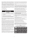
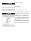
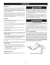
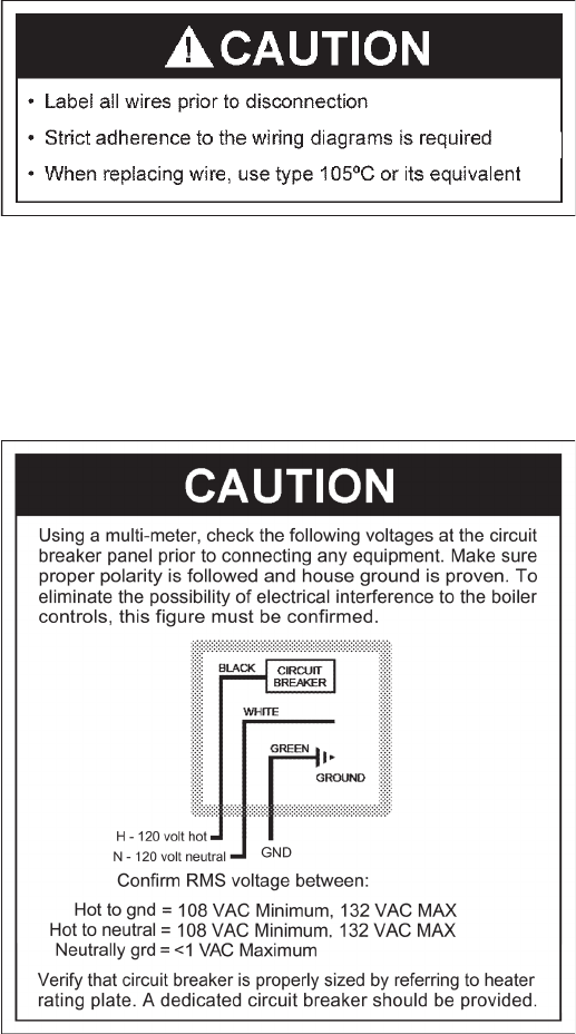
Label all wires prior to disconnection when servicing controls.
Wiring errors can cause improper and dangerous operation.
Verify proper operation after servicing. Strict adherence to the
wiring diagrams is required to prevent constant pump operation
whenthesystemcontrollerissatised.Otherwisethewarrantyis
void as stipulated in the limited warranty in this installation manual.
If any of the original wire, as supplied with the appliance, must be
replaced, it must be replaced with type 105°C wire or its equivalent.
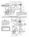
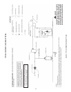
Figure 16.
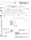
Therearefive(5)electricalconnectionsthatmustbemade
for the unit to operate correctly:
1.BLACK (NoStripe)120VHOT
2. WHITE 120V NEUTRAL
3. GREEN GROUND
4.(2)TANKPROBEOR(2)ENABLE/DISABLE***
*** Enable/disable can also be used with a 24 volt thermostat.
Do not use tank probe when using thermostat.
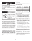
These connections shall be made at the rear of
the unit where a junction box is provided. AN
ELECTRICAL GROUND IS REQUIRED TO REDUCE
THE RISK OF ELECTRIC SHOCK OR POSSIBLE
ELECTROCUTION. A GROUND SCREW IS PROVIDED
IN THIS JUNCTION BOX.
NOTE: Tank probes are not provided on VB models,
it is required that a system/operating temperature
controller (field supplied) be installed to regulate
loop or system temperatures. Two yellow wires are
provided in the rear junction box for this connection.
Do not operate this boiler without system or
operating control.
When operating the boiler with the tank probe the enable/disable
must be wired together.
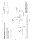
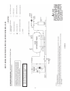
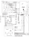
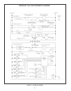
Refer to the Connection Diagram, see Figure 17, and to
the Schematic Diagram, see Figure 18.


Find Your Products By Category
Please Login
