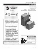

0
Owner's of the A.O. Smith Boiler 3400 gave it a score of 0 out of 5. Here's how the scores stacked up:
-
Reliability
0 out of 5 -
Durability
0 out of 5 -
Maintenance
0 out of 5 -
Performance
0 out of 5 -
Ease of Use
0 out of 5


Reliability
0
Out of 0 Ratings
When it comes to products, Reliability rates high in importance. Your Boiler’s ability to perform and maintain its functions during everyday use, as well as extreme use or under unexpected circumstances, is important when making purchase or repair decisions.


Durability
0
Out of 0 Ratings
How will your Boiler hold up over time and withstand the wear and tear of constant or long-term use? A product with strong Durability is a product that was made to last and provide a good ownership experience over it’s lifetime.


Maintenance 0
Out of 0 Ratings
Most Boiler owners intend to keep their Boiler in good working condition. Knowing up front if the Maintenance or repair of a product is easy or difficult can have a profound impact on your decision to make a purchase.


Performance 0
Out of 0 Ratings
Boiler's that are purchased and meet or exceed expectations usually share the trait of good Performance. Feeling that a product was worth the purchase because it does everything you expected, and does it well, is a clear indicator of a product that truly performs.


Ease of Use 0
Out of 0 Ratings
How hard is this Boiler to operate? If purchased, would tons of time be lost trying to figure out how it works? Simply put, Ease of Use is a measure of how easy a product is to use. Having this knowledge prior to purchase can help avoid buyer’s remorse.
Copy This Town Appliance Support Page to Share with a Friend
Find a Product
How it Works
Looking for the manual for a product you purchased at Town Appliance or researching before buying? You came to the right place.
Search for your Town Appliance product by entering the model number in the search bar above, or use the categories below to find your item.
Tired of losing your support information? Just add the manual for your Town Appliance product to your collection, and access it anytime.
